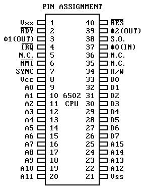
| PIN | DESC | FUNCTION |
|---|
| 1,21 | Vss | Ground.
|
| 2 | RDY | Ready. TTL level
input, used to DMA the 6502. The processor operates normally while RDY
is high. When RDY makes a transition to the low state, the processor
will finish the operation it is an, and any subsequent operation if it
is a write cycle. On the next occurrence of read cycle the processor
will halt, making it possible to tri-state the processor to gain
complete access to the system bus. |
| 3 | Phi1 | Phase 1 clock output. |
| 4 | IRQ |
The Interrupt Request input is a request that the processor initiate an
interrupt sequence. The processar will complete execution of the current
instruction before recognizing the request. At that time, the interrupt
mask in the Status Code Register will be examined. If the Interrupt Mask
is not set, the processor will begin an interrupt sequence. The Program
Counter and the Processor Status Register will be stored on the stack and
the interrupt disable flag is set so that no other interrupts can occur.
The processor will then load the Program Counter from the memory location
$FFFE and $FFFF.
|
| 6 | NMI | The Non-Maskable
Interrupt Request is a negative-edge sensitive request that the
processor initiate an interrupt sequence. The processor will complete
execution of the current instruction before recognizing the request.
|
| 7 | SYNC | The SYNC output is used in
conjunction with RDY to allow single instruction execution.
|
| 8 | Vcc | +5VDC input.
|
| 9-20,22-25 | A0-A15 | Address bus outputs.
Unidirectional bus used to address memory and I/O devices. |
| 26-33 | D0-D7 | Bi-directional
bus for transferring data to and from the device and the peripherals.
|
| 34 | R/W | The read/write line is a TTL
level output from the processor to control the direction of data transfer
between the processor and memory, peripherals, etc. This line is high for
reading memory and low for writing.
|
| 37 | Phi0 | Phase 0 clock input.
|
| 38 | S.O. | Set Overflow flag. A negative
going edge sets the overflow bit in the status code register. |
| 39 | Phi2 | Phase 2 clock output.
|
| 40 | RES | The Reset input is used to reset
or start the microprocessor from a power down condition. During the time
that this line is held low, writing to or from the microprocessor is
inhibited. When a positive edge is detected on the input, the microprocessor
will immediately begin the reset sequence. After a system initialization
time af 6 cycles, the mask interrupt flag will be set and the processor will
load the program counter from the contents of the memory location $FFFC and
$FFFD. This is the start location for program control. After Vcc reaches
4.75 volts in a power up routine, reset must be held low for at least 2
cycles. At this time the R/W line will become valid. |
